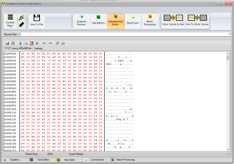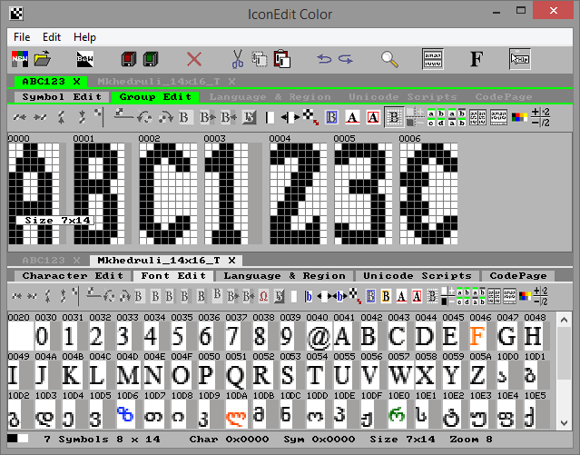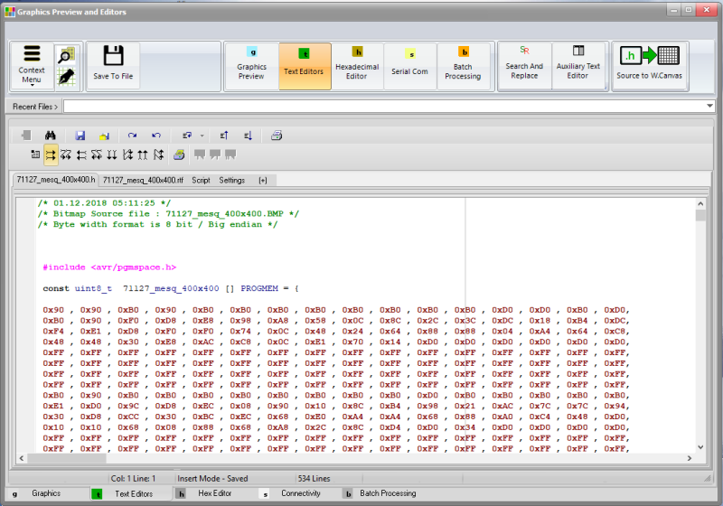

The GLCD bitmap editor tool is embedded into mikroElektronika’s compilers. It can generate a code equivalent of a BMP image, which can be easily inserted into the. Save bitmap files with the C format after converting their color palette, make pictures transparent, rotate or flip them, and invert the colors or pixels. GLCD Font Creator enables the creation of personalized fonts, symbols and icons for LCDs and GLCDs. Create fonts and symbols from scratch, or by importing existing fonts on your system. It lets you modify and adjust them for your needs, apply effects and finally export them as source code for use in mikroC, mikroBasic or mikroPascal compilers.
- Buy among 1000+ MikroElektronika original products: Compilers, Development boards, Add-on Boards, Programmers Debuggers and more.
- Generate GLCD Data arrays full screen, part of screen, screen subdivision. Data to text file, Intel Hex File, Binary File, 8,16 and 32 bit format. GLCD DATA COMPRESSION (monochrome only) LINK Imports Data Arrays of source files and convert data to bitmap inside the Work Canvas (monochrome only) LINK.


Graphic Lcd Library
The mikroC PRO for PIC provides a library for operating Graphic Lcd 128x64 (with commonly used Samsung KS108/KS107 controller).
For creating a custom set of Glcd images use Glcd Bitmap Editor Tool.
Library Dependency Tree
External dependencies of Graphic Lcd Library
| The following variables must be defined in all projects using Graphic Lcd Library: | Description : | Example : |
|---|---|---|
extern sfr char GLCD_DataPort; | Glcd Data Port. | char GLCD_DataPort at PORTD; |
extern sfr sbit GLCD_CS1; | Chip Select 1 line. | sbit GLCD_CS1 at RB0_bit; |
extern sfr sbit GLCD_CS2; | Chip Select 2 line. | sbit GLCD_CS2 at RB1_bit; |
extern sfr sbit GLCD_RS; | Register select line. | sbit GLCD_RS at RB2_bit; |
extern sfr sbit GLCD_RW; | Read/Write line. | sbit GLCD_RW at RB3_bit; |
extern sfr sbit GLCD_EN; | Enable line. | sbit GLCD_EN at RB4_bit; |
extern sfr sbit GLCD_RST; | Reset line. | sbit GLCD_RST at RB5_bit; |
extern sfr sbit GLCD_CS1_Direction; | Direction of the Chip Select 1 pin. | sbit GLCD_CS1_Direction at TRISB0_bit; |
extern sfr sbit GLCD_CS2_Direction; | Direction of the Chip Select 2 pin. | sbit GLCD_CS2_Direction at TRISB1_bit; |
extern sfr sbit GLCD_RS_Direction; | Direction of the Register select pin. | sbit GLCD_RS_Direction at TRISB2_bit; |
extern sfr sbit GLCD_RW_Direction; | Direction of the Read/Write pin. | sbit GLCD_RW_Direction at TRISB3_bit; |
extern sfr sbit GLCD_EN_Direction; | Direction of the Enable pin. | sbit GLCD_EN_Direction at TRISB4_bit; |
extern sfr sbit GLCD_RST_Direction; | Direction of the Reset pin. | sbit GLCD_RST_Direction at TRISB5_bit; |
Library Routines
Basic routines:
Advanced routines:
Glcd_Init
| Prototype | void Glcd_Init(); |
|---|---|
| Returns | Nothing. |
| Description | Initializes the Glcd module. Each of the control lines is both port and pin configurable, while data lines must be on a single port (pins <0:7>). |
| Requires | Global variables :
|
| Example |
Glcd_Set_Side
| Prototype | void Glcd_Set_Side(unsigned short x_pos); |
|---|---|
| Returns | Nothing. |
| Description | Selects Glcd side. Refer to the Glcd datasheet for detailed explanation. Parameters :
The parameter Note : For side, x axis and page layout explanation see schematic at the bottom of this page. |
| Requires | Glcd needs to be initialized, see Glcd_Init routine. |
| Example | The following two lines are equivalent, and both of them select the left side of Glcd: |
Glcd_Set_X
| Prototype | void Glcd_Set_X(unsigned short x_pos); |
|---|---|
| Returns | Nothing. |
| Description | Sets x-axis position to Parameters :
Note : For side, x axis and page layout explanation see schematic at the bottom of this page. |
| Requires | Glcd needs to be initialized, see Glcd_Init routine. |
| Example |
Glcd_Set_Page
| Prototype | void Glcd_Set_Page(unsigned short page); |
|---|---|
| Returns | Nothing. |
| Description | Selects page of the Glcd. Parameters :
Note : For side, x axis and page layout explanation see schematic at the bottom of this page. |
| Requires | Glcd needs to be initialized, see Glcd_Init routine. |
| Example |
Glcd_Read_Data
| Prototype | unsigned short Glcd_Read_Data(); |
|---|---|
| Returns | One byte from Glcd memory. |
| Description | Reads data from from the current location of Glcd memory and moves to the next location. |
| Requires | Glcd needs to be initialized, see Glcd_Init routine. Glcd side, x-axis position and page should be set first. See functions Glcd_Set_Side, Glcd_Set_X, and Glcd_Set_Page. |
| Example |
Glcd_Write_Data
| Prototype | void Glcd_Write_Data(unsigned short ddata); |
|---|---|
| Returns | Nothing. |
| Description | Writes one byte to the current location in Glcd memory and moves to the next location. Parameters :
|
| Requires | Glcd needs to be initialized, see Glcd_Init routine. Glcd side, x-axis position and page should be set first. See functions Glcd_Set_Side, Glcd_Set_X, and Glcd_Set_Page. |
| Example |
Glcd_Set_Ext_Buffer
| Prototype | void Glcd_Set_Ext_Buffer(char* (*getExtDataPtr)(unsigned long offset, unsigned int count, unsigned int *num)); |
|---|---|
| Returns | Nothing. |
| Description | Function sets pointer to the user function which manipulates the external resource. Parameters :
|
| Requires | Glcd module needs to be initialized. See the Glcd_Init routine. |
| Example |
Glcd_Fill
| Prototype | void Glcd_Fill(unsigned short pattern); |
|---|---|
| Returns | Nothing. |
| Description | Fills Glcd memory with the byte Parameters :
To clear the Glcd screen, use To fill the screen completely, use |
| Requires | Glcd needs to be initialized, see Glcd_Init routine. |
| Example |
Glcd_Dot
| Prototype | void Glcd_Dot(unsigned short x_pos, unsigned short y_pos, unsigned short color); |
|---|---|
| Returns | Nothing. |
| Description | Draws a dot on Glcd at coordinates ( Parameters :
The parameter Note : For x and y axis layout explanation see schematic at the bottom of this page. |
| Requires | Glcd needs to be initialized, see Glcd_Init routine. |
| Example |
Glcd_Line
| Prototype | void Glcd_Line(int x_start, int y_start, int x_end, int y_end, unsigned short color); |
|---|---|
| Returns | Nothing. |
| Description | Draws a line on Glcd. Parameters :
The parameter |
| Requires | Glcd needs to be initialized, see Glcd_Init routine. |
| Example |
Mikroelektronika 27s Glcd Bmp Editor Download 2017
Glcd_V_Line
| Prototype | void Glcd_V_Line(unsigned short y_start, unsigned short y_end, unsigned short x_pos, unsigned short color); |
|---|---|
| Returns | Nothing. |
| Description | Draws a vertical line on Glcd. Parameters :
The parameter |
| Requires | Glcd needs to be initialized, see Glcd_Init routine. |
| Example |
Glcd_H_Line
| Prototype | void Glcd_H_Line(unsigned short x_start, unsigned short x_end, unsigned short y_pos, unsigned short color); |
|---|---|
| Returns | Nothing. |
| Description | Draws a horizontal line on Glcd. Parameters :
The parameter |
| Requires | Glcd needs to be initialized, see Glcd_Init routine. |
| Example |
Glcd_Rectangle
| Prototype | void Glcd_Rectangle(unsigned short x_upper_left, unsigned short y_upper_left, unsigned short x_bottom_right, unsigned short y_bottom_right, unsigned short color); |
|---|---|
| Returns | Nothing. |
| Description | Draws a rectangle on Glcd. Parameters :
The parameter |
| Requires | Glcd needs to be initialized, see Glcd_Init routine. |
| Example |
Glcd_Rectangle_Round_Edges
| Prototype | void Glcd_Rectangle_Round_Edges(unsigned short x_upper_left, unsigned short y_upper_left, unsigned short x_bottom_right, unsigned short y_bottom_right, unsigned short round_radius, unsigned short color); |
|---|---|
| Returns | Nothing. |
| Description | Draws a rounded edge rectangle on Glcd. Parameters :
The parameter |
| Requires | Glcd needs to be initialized, see Glcd_Init routine. |
| Example |
Glcd_Rectangle_Round_Edges_Fill
| Prototype | void Glcd_Rectangle_Round_Edges_Fill(unsigned short x_upper_left, unsigned short y_upper_left, unsigned short x_bottom_right, unsigned short y_bottom_right, unsigned short round_radius, unsigned short color); |
|---|---|
| Returns | Nothing. |
| Description | Draws a filled rounded edge rectangle on Glcd with color. Parameters :
The parameter |
| Requires | Glcd needs to be initialized, see Glcd_Init routine. |
| Example |
Glcd_Box
| Prototype | void Glcd_Box(unsigned short x_upper_left, unsigned short y_upper_left, unsigned short x_bottom_right, unsigned short y_bottom_right, unsigned short color); |
|---|---|
| Returns | Nothing. |
| Description | Draws a box on Glcd. Parameters :
The parameter |
| Requires | Glcd needs to be initialized, see Glcd_Init routine. |
| Example |
Glcd_Circle
| Prototype | void Glcd_Circle(int x_center, int y_center, int radius, unsigned short color); |
|---|---|
| Returns | Nothing. |
| Description | Draws a circle on Glcd. Parameters :
The parameter |
| Requires | Glcd needs to be initialized, see Glcd_Init routine. |
| Example |
Glcd_Circle_Fill
| Prototype | void Glcd_Circle_Fill(int x_center, int y_center, int radius, unsigned short color); |
|---|---|
| Returns | Nothing. |
| Description | Draws a filled circle on Glcd. Parameters :
The parameter |
| Requires | Glcd needs to be initialized, see Glcd_Init routine. |
| Example |
Glcd_Set_Font
| Prototype | void Glcd_Set_Font(const char *activeFont, unsigned short aFontWidth, unsigned short aFontHeight, unsigned int aFontOffs); |
|---|---|
| Returns | Nothing. |
| Description | Sets font that will be used with Glcd_Write_Char and Glcd_Write_Text routines. Parameters :
The user can use fonts given in the file “__Lib_GLCDFonts” file located in the Uses folder or create his own fonts. List of supported fonts:
For the sake of the backward compatibility, these fonts are supported also:
|
| Requires | Glcd needs to be initialized, see Glcd_Init routine. |
| Example |
Glcd_Set_Font_Adv
| Prototype | void Glcd_Set_Font_Adv(const far char *activeFont, unsigned char font_color, char font_orientation); |
|---|---|
| Description | Sets font that will be used with Glcd_Write_Char_Adv and Glcd_Write_Text_Adv routines. |
| Parameters |
|
| Returns | Nothing. |
| Requires | Glcd needs to be initialized, see Glcd_Init routine. |
| Example | |
| Notes | None. |
Glcd_Set_Ext_Font_Adv
| Prototype | void Glcd_Set_Ext_Font_Adv(unsigned long activeFont, unsigned int font_color, char font_orientation); |
|---|---|
| Description | Sets font that will be used with Glcd_Write_Char_Adv and Glcd_Write_Text_Adv routines. Font is located in an external resource. |
| Parameters |
|
| Returns | Nothing. |
| Requires | Glcd needs to be initialized, see Glcd_Init routine. |
| Example | |
| Notes | None. |
Glcd_Write_Char
| Prototype | void Glcd_Write_Char(unsigned short chr, unsigned short x_pos, unsigned short page_num, unsigned short color); |
|---|---|
| Returns | Nothing. |
| Description | Prints character on the Glcd. Parameters :
The parameter Note : For x axis and page layout explanation see schematic at the bottom of this page. |
| Requires | Glcd needs to be initialized, see Glcd_Init routine. Use Glcd_Set_Font to specify the font for display; if no font is specified, then default |
| Example |
Glcd_Write_Char_Adv
| Prototype | void Glcd_Write_Char_Adv(unsigned char ch, unsigned int x, unsigned int y); |
|---|---|
| Returns | Nothing. |
| Description | Writes a char on the glcd at coordinates (x, y).
|
| Requires | glcd module needs to be initialized. See the Glcd_Init routine. |
| Example |
Glcd_Write_Text
| Prototype | void Glcd_Write_Text(char *text, unsigned short x_pos, unsigned short page_num, unsigned short color); |
|---|---|
| Returns | Nothing. |
| Description | Prints text on Glcd. Parameters :
The parameter Note : For x axis and page layout explanation see schematic at the bottom of this page. |
| Requires | Glcd needs to be initialized, see Glcd_Init routine. Use Glcd_Set_Font to specify the font for display; if no font is specified, then default |
| Example |
Glcd_Write_Text_Adv
| Prototype | void Glcd_Write_Text_Adv(unsigned char *text, unsigned int x, unsigned int y); |
|---|---|
| Returns | Nothing. |
| Description | Writes text on the glcd at coordinates (x, y). Parameters :
|
| Requires | Glcd module needs to be initialized. See the Glcd_Init routine. |
| Example |
Glcd_Write_Const_Text_Adv
| Prototype | void Glcd_Write_Const_Text_Adv(const far char *ctext, unsigned int x, unsigned int y); |
|---|---|
| Returns | Nothing. |
| Description | Writes text located in the program memory on the glcd at coordinates (x, y). Parameters :
|
| Requires | Glcd module needs to be initialized. See the Glcd_Init routine. |
| Example |
GLCD Bitmap Converter - Free Download And Software Reviews ...
Glcd_Image
| Prototype | void Glcd_Image(code const unsigned short *image); |
|---|---|
| Returns | Nothing. |
| Description | Displays bitmap on Glcd. Parameters :
Use the mikroC PRO for PIC integrated Glcd Bitmap Editor to convert image to a constant array suitable for displaying on Glcd. |
| Requires | Glcd needs to be initialized, see Glcd_Init routine. |
| Example |
Glcd_Ext_Image
| Prototype | void Glcd_Ext_Image(unsigned long image); |
|---|---|
| Description | Displays a bitmap from an external resource. |
| Parameters |
|
| Returns | Nothing. |
| Requires | Glcd needs to be initialized, see Glcd_Init routine. |
| Example | |
| Notes | Use the mikroC PRO for PIC32 integrated Glcd Bitmap Editor, Tools > Glcd Bitmap Editor, to convert image to a constant array suitable for displaying on Glcd. |
Glcd_PartialImage
| Prototype | void Glcd_PartialImage(unsigned int x_left, unsigned int y_top, unsigned int width, unsigned int height, unsigned int picture_width, unsigned int picture_height, code const unsigned short * image); |
|---|---|
| Returns | Nothing. |
| Description | Displays a partial area of the image on a desired location. Parameters :
Use the integrated Glcd Bitmap Editor (menu option Tools › Glcd Bitmap Editor) to convert image to a constant array suitable for displaying on Glcd. |
| Requires | Glcd needs to be initialized, see Glcd_Init routine. |
| Example |
Glcd_Ext_PartialImage
| Prototype | void Glcd_Ext_PartialImage(unsigned int x_left, unsigned int y_top, unsigned int width, unsigned int height, unsigned int picture_width, unsigned int picture_height, unsigned long image); |
|---|---|
| Description | Displays a partial area of the image, located on an external resource, on a desired location of the screen. |
| Parameters |
|
| Returns | Nothing. |
| Requires | Glcd needs to be initialized, see Glcd_Init routine. |
| Example | |
| Notes | Use the mikroC PRO for PIC32 integrated Glcd Bitmap Editor, Tools > Glcd Bitmap Editor, to convert image to a constant array suitable for displaying on Glcd. |
Library Example
The following example demonstrates routines of the Glcd library: initialization, clear(pattern fill), image displaying, drawing lines, circles, boxes and rectangles, text displaying and handling.
Mikroelektronika 27s Glcd Bmp Editor Download 1
HW Connection
How To Use MikroElektronika’s GLCD Bitmap Editor Tool To ...
Glcd HW connection
Mikroelektronika 27s Glcd Bmp Editor Download 2020
What do you think about this topic ? Send us feedback!